vapour recovery system ppt
Recommend Products
Vapor recovery Wikipedia
Vapor recovery is also used in the chemical process industry to remove and recover vapors from storage tanks. The vapors are usually either environmentally hazardous, or valuable to be recovered. The process consists of a closed venting system from the storage tank ullage space to a vapor recovery unit (VRU) which will recover the vapors for return to the process or destroy them, usually
Presentation of Vapour Recovery Systems M.P. Engg
→Determination of the pressure drop of the VRU and the vapour collecting system →Determination of the lines size, carbon bed diameter All vapours have to pass through the VRU.
GASOLINE DISTRIBUTION FACILITIES
VAPOR RECOVERY SYSTEMS: Stage 1 : Capture vapors during transfer at marine terminals, truck loading racks, bulk terminals and at retail gas stations Stage 2: Capture vapors during fueling vehicles at retail gas stations
Gas Compression and Vapor Recovery Systems Aereon
Gas Compression and Vapor Recovery Systems AEREON is one of the world’s largest manufacturers and service providers for carbon and compression based vapor recovery units (VRUs). Since 1980, our Jordan Technologies division has designed, manufactured and serviced VRUs across multiple industries, including liquid loading terminals, O&G production and midstream distribution, and gasoline stations.
6 installing vapor recovery US EPA
For 5 years Devon employed the Vapor Jet system and recovered more than 55 MMcf of gas from crude oil stock tanks Prior to installing the system, tank vapor emissions were ~ 20 Mcfd Installed a system with maximum capacity of 77 Mcfd anticipating production increases Revenue was
Flash Vapour Calculation Flash Vapour Recovery Vessel
The flash vapour recovery is one of the important energy conservation system in all process industries. Simple we can say that flash pot is one of the energy conservation device. The flash pot having compartments with different pressures. The comportment connected to subsequent bodies of evaporator
Flash Vapour Calculation Flash Vapour Recovery Vessel
The flash vapour recovery is one of the important energy conservation system in all process industries. Simple we can say that flash pot is one of the energy conservation device. The flash pot having compartments with different pressures. The comportment connected to
Enhanced Vapor Recovery Technology Review Workshop
Enhanced Vapor Recovery Technology Review Workshop PowerPoint PPT Presentation The presentation will start after a short (15 second) video ad from one of our sponsors.
1. Need for Tanker Vapor Recovery JFE Eng
9High Recovery Rate : 95% 9Compact & Simple Plant Configuration 9Wide Selection of Absorbent AL, AXL, AM & AH 9Pre Absorption Process VOC is absorbed to Absorbent. 9Membrane Separation Process Enrich VOC content of recycle gas. 9The process was developed in 1980s by JFE 9A lot of track records for gasoline vapor.
6 Installing Vapor Recovery Units authorSTREAM
Types of Vapor Recovery Units Conventional vapor recovery units (VRUs) Use rotary compressor to suck vapors out of atmospheric pressure storage tanks Require electrical power or engine Venturi ejector vapor recovery units (EVRUTM) or Vapor Jet Use Venturi jet ejectors in place of rotary compressors Do not contain any moving parts EVRUTM requires source of high pressure gas and intermediate
Vapour Recovery Systems Flotech Performance Systems
A basic vapour recovery unit system comprises a pressure swing absorption (PSA) process with two activated carbon bed vessels, alternating on a 15 minute time cycle. Regeneration of the carbon reactors is accomplished primarily by vessel evacuation with a vacuum pump to a pressure level of 27 Hg (3 Hg absolute) and secondly, with ambient air
Vapour Recovery System UK Petrol Diesel Petrochemicals
The prevailing method of vapour recovery globally is, and has been for decades, adsorption of the VOCs (volatile organic compounds VOC are chemicals that have high vapour pressure like Petrol, Diesel, Methanol, Crude Oil, Benzene, paints and ) onto activated carbon.Following adsorption, the activated carbon is regenerated by applying vacuum to these, the so called pressure swing
VOC recovery Systems IPIECA
On storage ships, the VOC recovery systems can reduce nmVOC emissions by more than 90%. There are two generic approaches to VOC recovery, known as ‘active’ and ‘passive’ VOC recovery technology. Active vapour recovery unit (VRU) systems typically include a compression step followed by condensation, absorption and/or adsorption.
Vapour Recovery for Petrol Filling Stations
A vapour recovery system helps to collect petrol vapour released during unloading and refueling back to the petrol tanker and underground storage tank, respectively. [Click to slide show] How do I know which stations have refueling vapour recovery system? If a station has installed this vapour recovery system which passes the required tests, it
Vapor Recovery Unit (VRU) Hy Bon
Since that time, HY BON/EDI has evolved into a global leader in vapor recovery, in this market, with more onshore vapor recovery unit (VRU) installations than the next three competitors in this market combined. HY BON/EDI vapor recovery units (VRU's) currently operate in over 20 countries, with a strong reputation for quality and reliability.
OPW VaporSaver™ Stage II Vapor Recovery System Censtar
The OPW VaporSaver™ Stage II Vapor Recovery System from OPW Fueling Components uses membrane technology to separate gasoline vapors into fuel and clean air, and is a major component in OPW's
Vapour recovery at service stations
Why we need vapour recovery at service stations The petrol vapours from vehicles and service stations are a big contributor to poor air quality in NSW. Petrol vapours contain Volatile Organic Compounds (VOCs) including benzene, xylene and toluene.
Vapour Processing System IPCO Power
The Vapour Processing System (VPS) is designed to reduce the VOC emissions with 99,9%. At the same time the VPS contributes to the sustainable development of bulk handling companies by reducing their electricity consumption.
Vapor Recovery California Air Resources Board
The California Air Resources Board’s (CARB) Vapor Recovery Program controls vapor emissions from gasoline marketing operations (gasoline dispensing facilities or service stations, tanker trucks (cargo tanks), bulk plants, and terminals), where gasoline vapor is a precursor to the formation of ozone and contains benzene, a constituent of gasoline vapor that has been identified as a toxic air
Vapour recovery Vapour recovery developments in Zeeco,
Vapour recovery emission is approximately 1g(HC)/Nm3, below which, more fuel would be used to run the vapour recovery unit than VOCs recovered from operating the system. This figure is of course very subjective dependent on factors including the product loaded and the utilisation of the vapour recovery system, amongst others.
6 installing vapor recovery US EPA
Reducing Emissions, Increasing Efficiency, Maximizing Profits Slide 6 Types of Vapor Recovery Units Conventional vapor recovery units (VRUs) Use rotary compressor to suck vapors out of atmospheric pressure storage tanks Require electrical power or engine Venturi ejector vapor recovery units (EVRUTM) or Vapor Jet
Vapour Recovery System Kilburn
The basic system of gasoline vapour recovery unit works on the principle of Pressure Swing Adsorption (PSA). The PSA system consists of two carbon vessels to ensure continuous operation. One adsorber vessel is always on stream in adsorption (separation) mode, whereas other adsorber is in desorption (recovery) mode.
PPT Enhanced Vapor Recovery Amendments Workshop
Enhanced Vapor Recovery Amendments Workshop PowerPoint PPT Presentation The presentation will start after a short (15 second) video ad from one of our sponsors.
Refrigerant Recovery, Evacuation and Charging Procedure
11. When the gauges indicate a 4” HG system vacuum has been achieved, close the recovery cylinder hand valve and shut off the recovery pump. 12. Remove the high and low side hoses and shut off valves from the access valves and attach to the manifold ports.
Vapour Recovery Flotech Performance Systems
Vapour Recovery You are here: Home / Vapour Recovery Whether you require a new vapour recovery unit or want to maximise the performance of your existing system, we have the products and experience to deliver.
DNVGL CG 0042 Cargo vapour recovery systems
Cargo vapour recovery systems DNV GL AS SECTION 6 SYSTEM ARRANGEMENTS 1 Arrangements The temperature of flammable gas or liquid in any vapour recovery system shall not exceed 220oC, unless means are provided to prevent auto ignition in the
PowerPoint Presentation
Vapor recovery lines, vent, and safe suction piping installed before J are not subject to H&SC Fill Risers Vent and fill risers are not subject to if the UST was before J and has either a ball float that restricts flow 30 min’s prior to overfill and allows no more than 95% capacity, or a flapper valve which shuts off the flow at 95%.
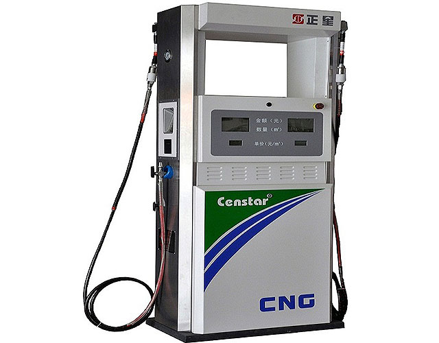
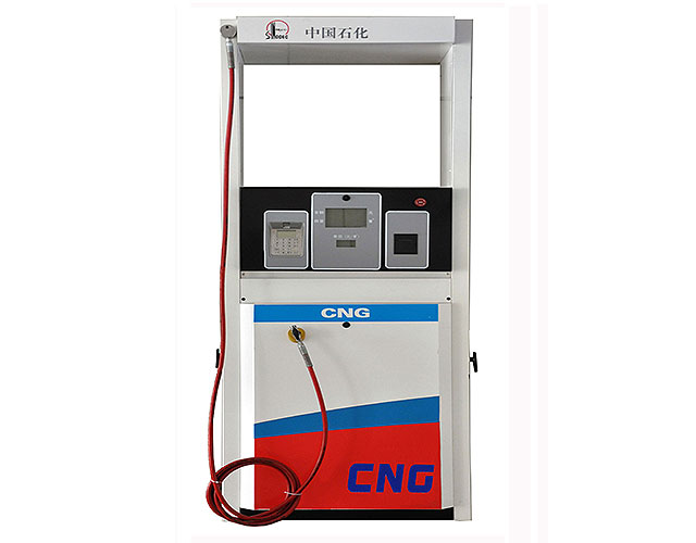
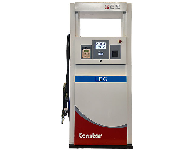
vapour recovery system Quality Supplier from China
Quality vapour recovery system supplier on sales from vapour recovery system manufacturer find China vapour recovery system factory, suppliers from
Standards and Best Practice Guidelines for Vapour Recovery
Standards and Best Practice Guidelines for Vapour Recovery at Petrol Service Stations 1 1 Introduction 1.1 Purpose of this document This document, entitled Standards and Best Practice Guidelines for Vapour Recovery at Petrol Service Stations (Standards and Guidelines), has three functions: 1.
SULFUR RECOVERY UNIT DESIGN SlideShare
Tail Gas: Contains N2, CO2, H2O, CO, H2, unreacted H2S and SO2, COS, CS2, sulfur vapor, etc. Limits overall sulfur recovery efficiency to 96 97% Tail gas is incinerated or treated in TGCU depending on local EPA regulation Incineration < 5000 ppmv H2S < 2500 ppmv SO2 TGCU Processes (Tail Gas Clean Up) higher H2S conversion efficiencies (>99.9
STAGE II VAPOUR RECOVERY
vapour recovery nozzles, vapour control valves, COAX hose assemblies, Safety Breaks and other accessories for Stage II vapour recovery. Some advantages of the ELAFLEX VR products are: n reliable products with a life expectancy of 10 years or more n slim design, lightweight and customer friendly n modular construction and interchangeable spare parts
Vapor Recovery Unit (VRU) Compressor Assembly Censtar
This Vapor Recovery Unit is an integrated plug and play system that requires minimal maintenance, but not every VRU is the same. It's a complex highly engineered system
Vapour Recovery Nozzles Franklin Fueling Systems India
The ON/OFF vapour path model is for use with multi nozzle dispensers. This model will automatically sense which nozzle is in use and close the vapour return path in the idle nozzles, preventing clean air from being pulled into the system. The Open Vapour Path model is for use with single nozzle dispensers equipped with vapour recovery equipment.
The Automatic Monitoring System for active Vapour
The Automatic Monitoring System for active Vapour Recovery VAPORIX Flow, Control and Master Product information The automatic monitoring sys tem VAPORIX supplies infor mation on the functional state of the active vapour recovery and thus fulfils the require ments of the 21.BlmSchV (Ger man directive). As an automa tic monitoring system for the
PowerPoint Presentation
A recovery/recycling refrigerant machine removes refrigerant from the system and recycles the refrigerant for reuse. Antifreeze Recovery and Recycling Equipment The mixture of antifreeze and water in a vehicle’s cooling system will eventually need to be replaced.
Overview of Vapor Absorption Chilling Systems
Vapor absorption systems work with non CFC refrigerants such as water or ammonia. Refrigerant of Li Br Absorption Machine is pure (distilled) water. The refrigerant water flows in a closed loop and is re circulated. These systems find acceptability in the commercial air conditioning or process cooling.
NH Stage I/II Vapor Recovery Program
Benefits of Gasoline Vapor Recovery Reduces VOC emissions by up to 95 percent. Reduces exposure to toxics and carcinogens. GASOLINE
Principles and Pressure Drop Calculation in Multiple
In this article discussed about history of multiple effect evaporator, Rillieux’s principles for multiple effect evaporator bodies and distribution of pressure drops across the multiple effect evaporators like Triple effect, Quadruple effect and Quintuple effect and also given online calculator for pressure drop calculation in multiple effect evaporator with values of latent heat and
Summary Guidance Note for Service Station Operators on
Station Operators on Petrol Vapour Recovery Requirements under PPC The purpose of this note is to provide brief guidance on the steps which operators will be required to take in order to comply with a PVR Standard Rules Permit issued by SEPA under the Pollution Prevention & Control (Scotland) Regulations 2000. Operators requiring more
Flare gas recovery system MPR Industries
Flare gas recovery system. We will design, manufacture and install a bespoke system that absolutely fits our customers’ needs and gas characteristics. We can supply either a compressor (single or multi stage sliding vane, or single stage liquid ring technologies) or a plug and play skidded Flare Gas Recovery Unit.
Vapor Recovery Unit (VRU) Hy Bon
QSG225 Standard VRU Compressor. The HY BON/EDI QSG225 VRU is our standard oil flooded screw compressor package engineered for larger volume tank vapor recovery applications. Our QSG225 packages have a gas volume range starting at 70 MSCFD and maxing out at 300 MSCFD. The unit is powered by a 75 horsepower electric motor and is engineered for up to 2% H2S concentration.
GAS FLARING IN INDUSTRY: AN OVERVIEW Robert B.
gas generates mainly water vapour and CO 2. Efficient combustion in the flame depends on achieving good mixing between the fuel gas and air (or steam) [9], and on the absence of liquids. Low pressure pipe flares are not intended to handle liquids and do not perform effi ciently when hydrocarbon liquids are released into the flare system [10].
IPCO Power Fuel Treatment and Vapour Recovery
IPCO Power BV Spinel 400 3316 LG Dordrecht The Netherlands IPCO Power provides the shipping, power and petrochemical industry with environmental solutions for Fuel Treatment and Vapour Recovery.
My Recovery System
The integration of My Recovery System’s easy to use, full back office platform and Vendor Transparency Solutions’ web based compliance management system with MBSi’s assignment volume, operating excellence and talent, formalizes a game changing component of
Vapour recovery units Guidance on preventing and
VAPOUR RECOVERY UNITS GUIDANCE ON PREVENTING AND CONTROLLING TEMPERATURE EXCURSIONS IN CARBON BEDS iv FOREWORD This second edition, has been prepared by the EI’s Vapour Recovery Working Group, in consultation with vapour recovery unit (VRU) suppliers and the UK Health & Safety Executive.
Automatic Controls for Industrial Refrigeration Systems
REFRIGERATION & AIR CONDITIONING DIVISION Automatic Controls for Industrial Refrigeration Systems Application Handbook MAKING MODERN LIVING POSSIBLE
Public Workshop to Discuss If Updates are Needed to the
impair effectiveness of vapor recovery system in controlling motor vehicle emissions Conduct a public workshop once every three years to review VRED List and to update as necessary Review VRED List when a written request is submitted Legal Requirements 4
Nozzles for Active Vapour Recovery Systems
4. Vapour Recovery Test Confirm the vapour recovery rate is in the acceptable range by performing either a wet or dry test described in the “Nozzle Vapour Recovery Testing” section of this manual. Nozzle Operating Instructions 1. Insert the spout into the fill neck of the vehicle. 2. Lower the hose end of the nozzle so the spout engages the
PPT Heat Recovery System PowerPoint presentation free
Heat Recovery System MEBS6008 Heat Recovery Heat recovery in water cooled centrifugal chillers Auxiliary Condenser 2 An auxiliary condenser heat recovery chiller A free PowerPoint PPT presentation (displayed as a Flash slide show) on id: 3f3449 N2Y2N
Heat Recovery System in Domestic Refrigerator SlideShare
Figure shows Vapour Compression Refrigeration Cycle Figure 2.1 shows a typical vapour compression refrigeration system that can be broken into the different processes as explained below: Process 1 2 Low pressure liquid refrigerant in the evaporator absorbs heat from its surroundings, usually air, water or some other process liquid.
Ejector Vapour Recovery Unit Crystal TCS
Ejector Vapour Recovery Unit are relatively new to this field, but are rapidly gaining acceptance over conventional recovery systems. We at Crystal TCS have performed intensive research and development for coming up with Ejector Solutions for Vapour Recovery Units.
Chapter 10 Refrigerant Recovery, Recycling Cylinders UNEP
1. Pump out refrigerant using System compressor as vapour (if service valve used) or as liquid from condenser exit 2. System compressor should not run below “0” PSIG 3. Higher percentage of recovery possible 4. Still, significant percentage of refrigerant will be left in the system Accelerated Passive Recovery using System Compressor
Vapour Recovery Inspection and Testing Stage 1B Vapour
The vapour recovery system will have one tanker connection point which can be below or above ground which will come complete with a poppet self sealing adaptor and a flame arrester approved to EN ISO 16852. The petrol vent lines will then be manifolded together, this can take place above or below ground allowing vapour to be returned from all
Vapour Recovery
DRYVac™ is the first vapor recovery system to be normally offered with both inlet and outlet hydrocarbon monitoring systems. We believe that every process system should be fitted with enough instrumentation so it can adjust to the inlet conditions and monitor its effluent.
FUEL DISPENSING AND VAPOUR RECOVERY VALVES
FUEL DISPENSING AND VAPOUR RECOVERY VALVES APPLICATIONS FOR FUEL DISPENSING SYSTEMS To propel a vehicle, a combustible com pound is needed. ASCO Numatics is well known as solenoid valve supplier for the dispensers as the combustible compound is: • Petrol • Diesel (including vapour recovery) • Liquefied Petroleum Gas (LPG)
Aboveground Storage Tanks (AST) Phase II Enhanced Vapor
Vapor Recovery Throughput ofFacilities (gallons/year) Facilities Subjectto Phase II EVR (VR‐501) Throughput of Facilities Subject to Phase II EVR 2,761 106,782,636 187 55,536,802 Upgrade to Phase II EVR Breakdown Cost Average System Equipment Cost:
Vapour Recovery System Savas
Vapour Recovery System. GET A QUOTE. Water in the active parts of the transformer can have adverse effect on its lifetime. The indicative lifetime of insulation at 80 C and 1% moisture is around 40 years whereas with 3% moisture it is 10 Years. Furthermore the reliability and overload capacity of the transformer are also affected when moisture
8. WASTE HEAT RECOVERY Bureau of Energy Efficiency
8. Waste Heat Recovery Bureau of Energy Efficiency 174 TABLE 8.1 WASTE SOURCE AND QUALITY . Source Quality 1. Heat in flue gases. The higher the temperature, the greater the potential value for heat recovery 2. Heat in vapour streams. As above but when condensed, latent heat also recoverable. 3.
Overview of Vapor Absorption Cooling Systems
recovery and cogeneration system help reduce problems related to greenhouse effect from CO 2 emission. Vapor absorption system allows use of variable heat sources: directly using a gas burner, recovering waste heat in the form of hot water or low pressure steam, or boiler generated hot water or steam. The Basic Principle of Absorption Cooling
Vapour Recovery System Alfons Haar
The closed vapour recovery system prevents emission of any vapours. • If the vacuum in any tank compartment exceeds 15mbar, the vapour transfer safety valve opens automatically. • The vapour recovery system as described permits safe simultaneous bottom loading with up to 5 loading arms at any depot designed to VOC Directive 94/63/EC. Note
Waste heat recovery Alfa Laval
Heat pumps and mechanical vapour recompression (MVR) Heat pumps and MVRs are used when the temperature of the waste heat stream is too low to be used for heat recovery. Both heat pumps and MVRs raise the temperature of the waste heat, but require an input of electricity or mechanical work (for driving a compressor).
Vapour Control on Crude Oil Loading Platts
©2013 John Zink Company, LLC CONFIDENTIAL AND PROPRIETARY 11 Vapour Recovery System Carbon Adsorption Absorption (ADAB™) Advantages: Worldwide acceptance as the standard for gasoline Vapour