
stage 1b vapour recovery system
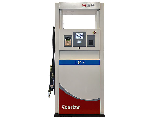
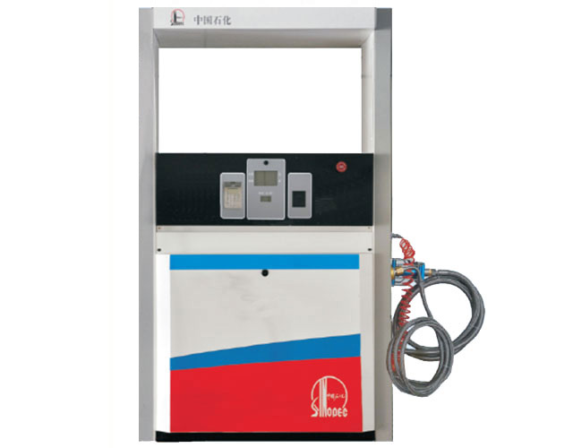
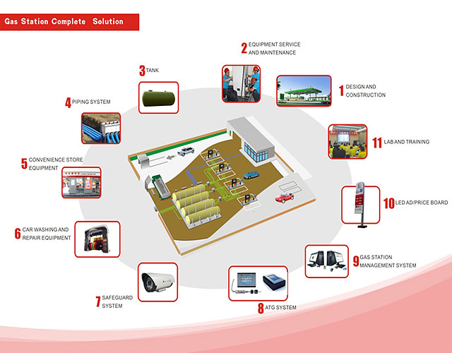
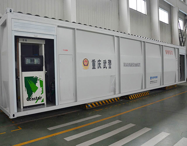
Recommend Products
Vapour Recovery Inspection and Testing Stage 1B Vapour
The basic principle of stage 1B vapour recovery is to control the vapour released from the filling station storage tanks during the unloading procedure from the road tanker. This is achieved by diverting the vapour displaced through the tank vent back to the road tanker for removal from site and subsequent recovery at the distribution terminal.
Gasoline Vapor Recovery (Stages I and II) TCEQ www
Stage II Vapor Recovery System Enforcement Discretion Directive. GDFs currently equipped with Stage II systems must continue to comply with existing Stage II requirements in 30 TAC Part 1, Chapter 115, Subchapter C, Division 4 . Also, GDFs that meet the requirements of this directive must continue to comply with the Stage I requirements in 30 TAC
Stage I Vapor Recovery Petroleum Equipment Institute
Stage I Vapor Recovery A system designed to capture displaced vapors that emerge from inside a storage tank when a load of gasoline is delivered into the tank. During the filling process, the rising liquid displaces the vapors present in the upper portion of the tank.
Stage 1 Vapor Recovery Test Results Form Connecticut
This Stage 1 Vapor Recovery Test Results report will be considered incomplete unless the required signature is provided. I certify that I have been authorized by the owner or operator of the GDF site listed in Part I of this form to test the Stage I Vapor Recovery System and submit the test results to the CT DEEP on their behalf.
EPA Stage 1 Vapor Recovery Gasoline Dispensing
The U.S. EPA has produced a video to help petroleum marketers better understand and comply with EPA's vapor control regulation known as National Emission Standards for Hazardous Air Pollutants for
Vapour recoVery solutions from sGs oil, Gas and chemicals
Vapour recoVery unit Vru start siGnal from loadinG control system clean air <35G/m3 petrol Vapour Stage 1A Vapour recovery at distribution terminals Stage 1A vapour recovery concerns the control and elimination of unwanted emissions of petrol vapour that occur at distribution terminals. Legislation now in force requires that steps are taken to
Stage 1 Vapor Recovery Test Results Form Connecticut
Stage I Vapor Recovery System and submit the test results to the CT DEEP on their behalf. This Stage 1 Vapor Recovery Test Results report will be considered incomplete unless the
EPA Stage 1 Vapor Recovery Gasoline Dispensing
The U.S. EPA has produced a video to help petroleum marketers better understand and comply with EPA's vapor control regulation known as National Emission Standards for Hazardous Air Pollutants for
VAPOUR RECOVERY Kalymnos Fuel Engineering
The Vapour Recovery Couplers ensure the opening and vapor transfer through the VR Adaptor of the road tanker. The KFE has Couplers for both VRU of the loading gantry and for the vapor transfer piping to
Code of practice for petroleum road tanker vapour
CODE OF PRACTICE FOR PETROLEUM ROAD TANKER VAPOUR COLLECTION SYSTEMS AND EQUIPMENT USED IN UNLOADING OPERATIONS 1 European Parliament and Council Directive 94/63/EC of 20 December 1994 on the control of volatile organic compound (VOC) emissions resulting from the storage of petrol and its distribution from terminals to service stations.
STAGE II VAPOUR RECOVERY
At the heart of the vapour recovery system is the device used to control the volume of vapour recovered relative to the liquid dispensed. Both have to correspond. To achieve the correct ratio, it is necessary to control the vapour volume flow. ALTERNATIVE 1: The proportional valve GRVP controls the
Vapor Recovery Test Procedures Handbook
December, 2002 RG 399. Vapor Recovery Test Procedures Handbook . Field Operations Division . printed on . TEXAS COMMISSION ON ENVIRONMENTAL QUALITY. recycled paper
Stage II Vapour Recovery
capture petrol vapour displaced from underground storage tanks (Stage 1b) when they are filled. Under UK legislation sites with petrol sales above 3.5 million litres per annum are installing petrol vapour recovery during refuelling of passenger cars (Stage II) before
Oil & Gas Vapor Recovery Systems PetroGas Systems
Vapor Recovery. VOC and HAP emissions pollute the atmosphere and the air we breathe. Governmental agencies have mandated the control of these emissions. They can be controlled by destruction (incineration) or by recovery. PETROGAS offers systems for the recovery of emissions using absorption, refrigeration, or adsorption.
Summary Guidance Note for Service Station Operators on
PVR Stage I System Design Requirements The system must minimise petrol vapour emissions when the specified number of delivery tanker compartments are discharged at the same time. Petrol storage tank vent pipes must be fitted with a pressure vacuum relief valve.
Petrol Vapour Recovery Permit
The permit will also need to cover Stage 2 vapour recovery if the annual throughput of petrol at the station is, or is likely to be, 3500m3 or more. Service Stations that meet the above thresholds must apply for an Environmental Permit from the Local Authority. It is
Vapor Recovery Certification and Test Procedures
Stationary Source Test Methods, Volume 2, Certification and Test Procedures for Gasoline Vapor Recovery Systems, can be downloaded in two formats MS Word and Adobe Acrobat. The links in the table below provide access to individual sections of Volume 2 in uncompressed MS Word or Adobe Acrobat (.PDF) format.
EROS Easy Riser Berrys Fuelling Technologies : Berrys
Pressure vacuum valves are required on all sites with Stage 1 vapour recovery systems. The pressure vacuum(PV) valve allows a slight build up of pressure vapour in the tank farm and greatly reduces the free flow of volatile organic compounds to atmosphere.
AQ05(08) Additional Guidance from Defra and the Welsh
atmosphere through the filler neck of the fuel tank. Stage II controls will capture the majority of the emissions. 5. Traditional active vapour recovery systems consist of a modified petrol delivery nozzle, coaxial hose and dispenser for all petrol sales. Petrol vapour in the vehicle fuel tank headspace is
Vapour Recovery Fittings Risbridger
Risbridger manufacture the patented and ATEX approved market leading Stage Two Vapour return line Shear Valve, as well as Pressure Vacuum Vent Valves
EPA Stage 1 Vapor Recovery Gasoline Dispensing
The U.S. EPA has produced a video to help petroleum marketers better understand and comply with EPA's vapor control regulation known as National Emission Standards for Hazardous Air Pollutants for
Bottom Loading and Vapor Recovery System Emco Wheaton
Vapor recovery is achieved by including a hood on the compartment vent valve and a Vapor Recovery Adaptor at the end of the vapor return pipe. The facility can be utilized for both stage 1A vapor recovery (recovery of vapors whilst loading) and stage 1B (whilst off loading).
Vapor Recovery Certification and Test Procedures
Stationary Source Test Methods, Volume 2, Certification and Test Procedures for Gasoline Vapor Recovery Systems, can be downloaded in two formats MS Word and Adobe Acrobat. The links in the table below provide access to individual sections of Volume 2 in uncompressed MS Word or Adobe Acrobat (.PDF) format.
FUEL DISPENSING AND VAPOUR RECOVERY VALVES
STAGE I SYSTEM STAGE II SYSTEM The 'Stage I' vapour recovery has been in place for a number of years at storage terminals and at filling stations, to recover vapours that would normally escape into the atmosphere during the filling of storage tanks. OTHER GRADES FUEL METER PETROL PUMPING UNIT FUEL INLET VAPOUR RETURN TO TANK VAPOUR PUMP & MOTOR ASSEMBLY
CP 201, Procedure for Vapor Recovery Systems at Gasoline
the Phil Tite Phase I Vapor Recovery System, including modifications, conforms with all of the requirements set forth in the Certification Procedure, and results in a vapor recovery system which is at least 98.0 percent efficient as tested in accordance with test procedure
Vapor Recovery Test Procedures Handbook
December, 2002 RG 399. Vapor Recovery Test Procedures Handbook . Field Operations Division . printed on . TEXAS COMMISSION ON ENVIRONMENTAL QUALITY. recycled paper
Petrol Filling Stations; Vapour Recovery
The course covers the types of Vapour Recovery Stage 1A, Stage 1B and Stage 2. There is an explanation of how Vapour Recovery has evolved and its legal requirements, applying for Permits and the extensive conditions imposed.
TESTING VAPOUR RECOVERY SYSTEMS Carter, Rodney
In a Stage 1B vapour recovery system, the common manifold is fitted with one or more p/v valves. For such a case, the vacuum operation of the p/v valve should be tested before the performance of the testing method, by having the shut off valve closed and checking for
Moving Away From Stage II Vapor Recovery
decommissions a Stage II vapor recovery system shall perform the decommissioning of the Stage II vapor recovery system in accordance with the “Recommended Practices for Installation and Testing of Vapor Recovery Systems at Vehicle Refueling Sites” of the Petroleum Equipment Institute, Sect .
Fuel Vapour Recovery DIYnot Forums
Benzene, for example, is a genotoxic human carcinogen. Petrol vapour recovery systems can be installed at service stations to reduce emissions of VOCs from vehicle refuelling; these are known as 'stage II' controls. It is proposed to implement stage II controls in the UK by a limited negotiated agreement with UK industry.
Tank Truck Equipment Soliflo
Vapour recovery is achieved by including a hood on the compartment vent valve and a vapour recovery adaptor at the end of the vapour return pipe. The facility can be utilised for both Stage 1A vapour recovery (recovery of vapours whilst loading) and Stage 1B (whilst off loading).
Metal PRV Tank Vent Valve Centre Tank Services
About the product. The Metal PRV Tank Vent Valve has an integrated poppet type valve designed to prevent fuel vapours from escaping under normal operating conditions. This Teflon coated aluminium pressure vacuum vent valve is fitted on top of risers on stage 1B
Environmental Health licences and permits Wiltshire Council
A permit covering Stage 1 vapour recovery will be required if the annual amount of petrol unloaded at the station is, or is likely to be, 500m 3 or more. The permit will also need to cover Stage 2 vapour recovery if the annual throughput of petrol at the station is, or is likely to be, 3500m 3 or more.
Vapor Recovery Systems Manufacturers, Suppliers
Find here information of Vapor Recovery Systems selling companies for your buy requirements. Contact verified Vapor Recovery Systems Manufacturers, Vapor Recovery Systems suppliers, Vapor Recovery Systems exporters wholesalers, producers, retailers and traders in India.
3AJG000747 019 vapor emission controls ABB Ltd
Stage 1b: The control of emissions during off loading at service stations. in the vapour collection system. 5. VAPOR RECOVERY UNITS 5.1 Types of vapor recovery units Vapor recovery units are devices, which separate hydrocarbons from air and convert them back into liquid. The main types of vapor recovery units on the market are:
Gaspendelschlauch GPS Vapour recovery hose GPS
Type GPS is a flexible, lightweight hose for Stage 1B balanced vapour recovery ( during the unloading of road tankers into the storage tank ). For the assembling, clamp type Spannloc or Spannfix fittings can be used. If the steel helix is connected at both ends, GPS is suitable for electronic filling cross over prevention systems.
VAPOUR RECOVERY ADAPTOR Industrial Flow Systems
of the recovery of vapours during stage 1A and 1B vapour recovery operations, this valve is internationally regarded as the bench mark for poppeted vapour recovery adaptors. WHEN SPECIFYING VAPOUR RECOVERY VALVES FOR YOUR VEHICLE, THE FOLLOWING POINTS SHOULD BE CONSIDERED: • Where is the valve to be mounted on the vehicle?
Vapour Recovery System Alfons Haar
The closed vapour recovery system prevents emission of any vapours. • If the vacuum in any tank compartment exceeds 15mbar, the vapour transfer safety valve opens automatically. • The vapour recovery system as described permits safe simultaneous bottom loading with up to 5 loading arms at any depot designed to VOC Directive 94/63/EC. Note
Metal PRV Tank Vent Valve
The Metal PRV Tank Vent Valve has an integrated poppet type valve designed to prevent fuel vapours from escaping under normal operating conditions. This Teflon coated aluminium pressure vacuum vent valve is fitted on top of risers on stage 1B vapour recovery systems and static tanks. Features of the Metal Pressure Vacuum Vent Valve:
Sec. . Testing Requirements, Chapter
C. Stage II Vapor Recovery System. (1) An owner of a Stage II vapor recovery system subject to this chapter shall repeat the required tests: (a) In accordance with the test schedule in §C(2) of this regulation; and (b) Upon replacement of 75 percent or more of an approved system. (2) Test Schedule.
The Total System Solution
product or vent/vapour piping, Franklin has the solution to fit any scenario and when you monitor your piping system using a Franklin fuel management system, you’re covered by an upgraded warranty. Dispensing Systems: Franklin Fueling Systems offers the world’s leading enhanced vapour recovery systems,
New vapour recovery offers savings
Petrol normally lost to delivery tankers equipped with stage 1B vapour recovery can now be retained says Petroman Environmental Services. “The Total Vapour Solutions system pays for itself, and begins to actually make money in a remarkably short time, simply by retaining petrol that would otherwise go back to the depot or refinery,” says Roger Bailey, sales manager of Petroman
Forecourt Maintenance Censtar Australia
Make sure your forecourt is compliant with our wide range of testing and certification services. Measure Checks & Self Verification. Electrical Testing. Vapour Recovery Stage 1b. Vapour Recovery Stage 2. Planned Preventative Maintenance Checks. Critical Safety Device Audits. Suction & Pressure Line Tests.
protective equipment PPE Emergency procedures Actions by
protective equipment (PPE) Emergency ∙ procedures Actions by ∙ authorised personnel (Store Manager) Concerned ∙ driver Storage of fuel on site Leak ∙ Uncontrolled ∙ vapour release ∙ Fire/explosion ∙ caused by ignition of vapour following uncontrolled release of product Secondary ∙ containment Leak detection system ∙ Observation/monitorin ∙ g well(s) Stage 1b vapour ∙ recovery Gauge systems ∙ Automated ∙
Environmental Health licences and permits Wiltshire Council
Controls to minimise vapour loss from the unloading of petrol into storage tanks are referred to as Stage 1 vapour recovery controls. Controls to minimise vapour loss from the filling of vehicle tanks are referred to as Stage 2 vapour recovery controls.
Risk Assessments for Petrol Filling Station Pembrokeshire
1m radius around vapour return hose connection point. 2m radius around tank venting points where the site has stage 1b vapour recovery installed. 2m radius from the edge on an oil separator (petrol interceptor). Within a 4.1 radius of a petrol delivery hose connection on a dispenser (with stage 2 vapour recovery in operation).
STATE OF DELAWARE DEPARTMENT OF NATURAL
performing California ARB test procedure is recommended.* Vapor Adapter (Stage I Swivel Adapter and Dry Break) OPW 61VSA Visually inspect the adapter for large dents, cracks, or deformations. Check the vapor poppet for damage and ensure that the poppet seats evenly with the adapter. Clean out any foreign objects from the vapor poppet’s
The Stage 1B Vapour Recovery System installed at the above site has been tested by the authorised engineer named above using the Petroman Testing Procedure. The results confirm that this Stage 1B Vapour Recovery System has PASSED. We confirm that the PV and VR valves have proven to be in good operational condition and meet
3AJG000747 019 vapor emission controls ABB Ltd
Stage 1b: The control of emissions during off loading at service stations. The control of emissions generated during automobile refueling can be undertaken either by using a system on board the automobile (e.g. carbon canister) or by modifying the
Metal PRV Tank Vent Valve
The Metal PRV Tank Vent Valve has an integrated poppet type valve designed to prevent fuel vapours from escaping under normal operating conditions. This Teflon coated aluminium pressure vacuum vent valve is fitted on top of risers on stage 1B vapour recovery systems and static tanks. Features of the Metal Pressure Vacuum Vent Valve:
The Stage 1B Vapour Recovery System installed at the above site has been tested by the authorised engineer named above using the Petroman Testing Procedure. The results confirm that this Stage 1B Vapour Recovery System has PASSED. We confirm that the PV and VR valves have proven to be in good operational condition and meet
Services Northern Pump Distributors
vapour recovery stage 1b maintenance We are able to carry out maintenance of the Vapour Recovery Stage 1B pipework on your petroleum installation. The maintenance includes visual inspection and checking of equipment for functionality.
Section 1: Petrol + Chemical Hoses
Vapour Recovery Hoses Stage 1b; Aircraft Refuelling Hoses; Liquefied Petroleum Gas Hoses; Chemical and Solvent Hoses; Universal Hoses Speciality Hoses; Pharma Hose Assemblies; Marine Hoses Bunkering Hoses; Hot Bitumen Hoses; Steam Hoses; Composite Hosesplease
Pump & Tank Gauge Fuel System Maintenance
Vapour Recovery. Using our nationwide fleet of cherry picker vehicles, we provide extensive UK coverage for Stage 1b and Stage 2 inspections, testing, adjustment and so certification.
The Total System Solution
• Stage 1b vapour recovery equipment • Shear valves Dispensing Submersible Pumping Transport Piping & Containment Piping & Containment Station Hardware Dispensing Systems Submersible Pumping Systems Transport Systems uel Manag Systems are the tings. nitoring systems, complete control of Service Station Hardware Fuel Management Systems
Vapor Recovery Systems Manufacturers, Suppliers
Gasoline vapour recovery systems designed, engineered and manufactured by KILBURN are backed by KILBURN’s extensive experience in process design, detail engineering and supply of adsorption systems and skid mounted units.
Design, construction, modification, maintenance and
The Energy Institute (EI) is the leading chartered professional membership body supporting individuals and organisations across the energy industry. With a combined membership of over 14 000 individuals and 300 companies in 100 countries, it provides an independent focal point for the energy community and a powerful voice to engage business and industry, government, academia and the public
Wetstock Reconciliation at Fuel Storage Facilities
underground water system and pollute the groundwater which in many cases provides drinking water to local communities. Given the significant risks to health & safety of people and the environment, the storage of petrol at retail & private stores is controlled by specific legislation which requires such
Apparatus and method for testing vapor recovery systems
A stage 1B vapour recovery system which is classified "not vapour tight" will facilitate fugitive vapour emissions from identified and unidentified vapour escape paths. Some or all of these vapour emissions may be considered leaks. If a stage 1B vapour recovery system is to be effective it must be vapour tight.
State of California AIR RESOURCES BOARD EXECUTIVE
certification procedures for systems designed for the control of gasoline vapor emissions during the filling of underground gasoline storage tanks (Phase I EVR system), in its Certification Procedure for Vapor Recovery Systems at Gasoline Dispensing Facilities
Section 1: Petrol + Chemical Hoses
Section 1: Petrol + Chemical Hoses . Download PDF. Fuelling Hoses without Helix "Yellow Band" for Petroleum based Products, Page 103‑104. Type HD (reel hose) Type HD RV (hose for flexible pipe joints) Stage 1b Vapour Recovery Hose, Type GPS, Page Info (Revision ) Type GPS;
Risk Assessments for Petrol Filling Stations Required
3. Stage 1b vapour recovery 4. Vent pipe location 5. Location/protection of fill pipes (tanker stand) 6. Impervious surface to tanker stand 7. Drainage of tanker stand/tank fill point area to a retention system. 8. Driver controlled delivery equipment 9. Adequate lighting 10. Hazardous area classification /