gas compressor station block diagram
Recommend Products
-
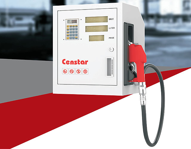
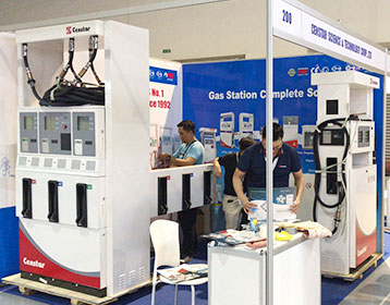
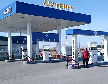
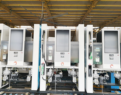
CS20 Series Fuel Dispenser
-
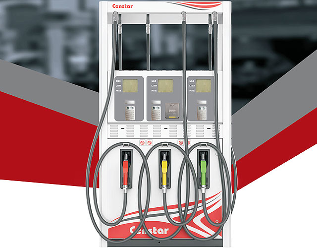
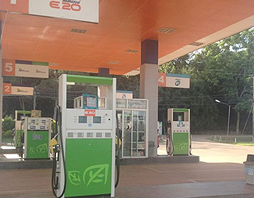
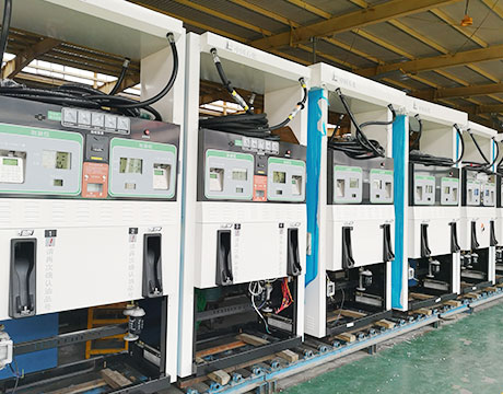
CS42-Legend Series Fuel Dispenser
-
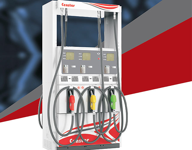
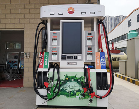
CS42-Classic Series Fuel Dispenser
-
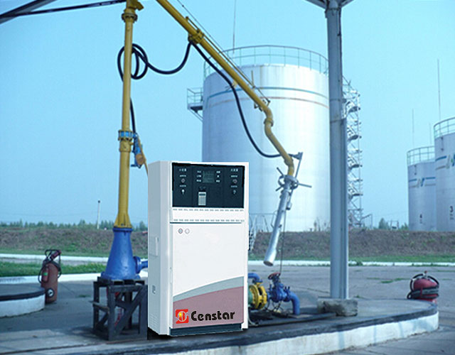
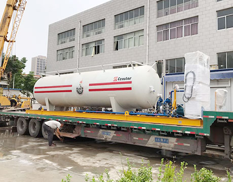
CNG Loading device / unloading device
-
LNG dispenser
-
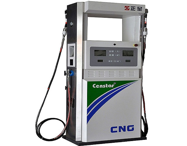
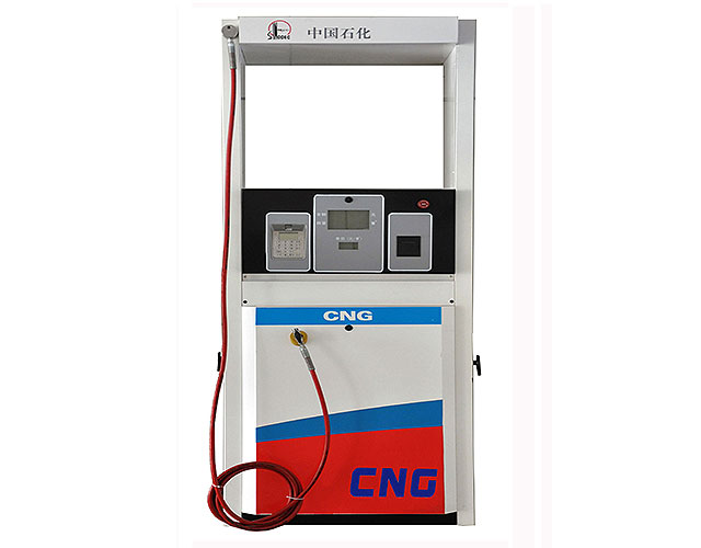
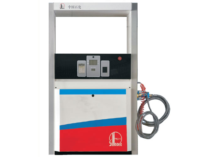
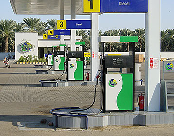
CNG Dispenser
-
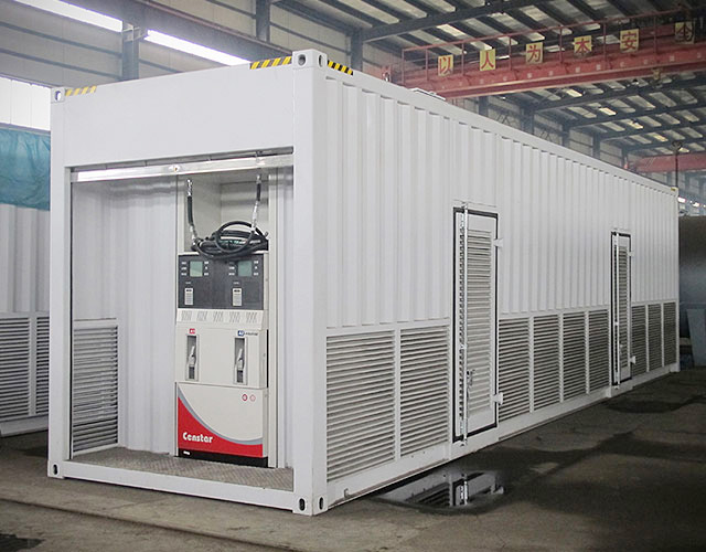
Censtar Mobile fuel station CSMF20(20000L)
-
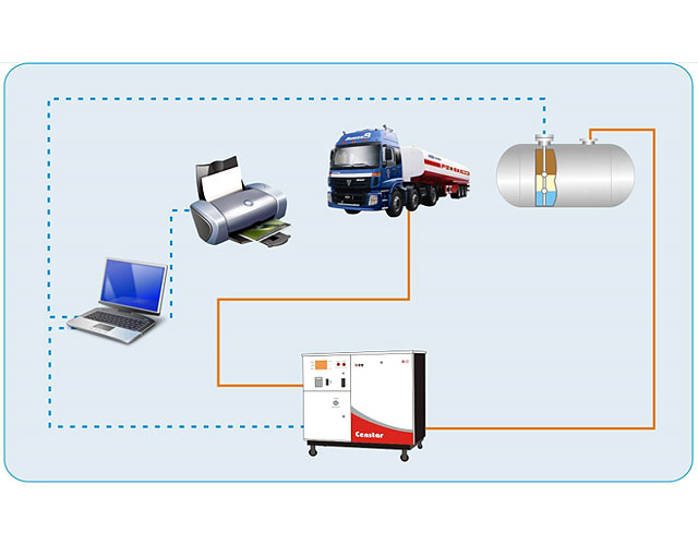
centralized type (for diesel only) Management system of oil depot
-
Tank Gauge & Calibration system
Hydrogen Fueling Station Cooper Union
The H 2 production technology that is employed in this plant is steam reformation. Steam reformation is the most established commercial method for H 2 production and it is also the cheapest. In this technique, the natural gas feedstock is reacted with high temperature steam to yield H
8.2. Typical IGCC Configuration
Figure 2 shows a simplified block flow diagram (BFD) illustrating the major process sub systems included in an IGCC plant. The BFD shows an elevated pressure (EP) air separation unit (ASU) integrated to the gas turbine (GT) operation by extracting some of the GT air compressor discharge as feed to reduce the ASU air compressor size and power
Engineering Standards Manual: Standard Drawings & Details
LANL Standard Drawings and Details either (1) depict required format/content or (2) are templates that are completed by a Design Agency (LANL or external AE) for a design drawing package, in a manner similar to specifications.
An Overview of Combined Cycle Power Plant
An open circuit gas turbine has a compressor, a combustor and a turbine. For this type of cycle the input temperature to turbine is very high. The output temperature of flue gases is also very high. This is therefore high enough to provide heat for a second cycle which uses steam as the working medium i.e. thermal power station.
Oil facility PetroWiki
Fig. 1 is a block diagram of a simple oil facility. Each of the blocks is described here, except for gas dehydration, which is covered in Gas Facilities. Fig. 1—Typical oil facility. the total liquid in the tank increases even further, with additional gas flashing at a higher pressure, reducing compressor
How Does the Natural Gas Delivery System Work? American
Compressor Stations. Compressor stations are located approximately every 50 to 60 miles along each pipeline to boost the pressure that is lost through the friction of the natural gas moving through the steel pipe. Many compressor stations are completely automated, so the equipment can be started or stopped from a pipeline's central control room.
US8052398B2 Reciprocating gas compressor with speed
FIG. 1 is a block diagram of a reciprocating gas compressor system. FIG. 2 illustrates the piping response to pulsation of an example compressor system. FIG. 3 illustrates the piping response of the example compressor system, with the compressor operating at the worst case fixed engine speed.
Compressed Air System Schematic Diagram
Most air Fig 3: Schematic diagram of Solar based air compressor for inflating tyres. to compressor, t2 compressed air temperature, tg3 temperature of the Diagram of a system with heat regeneration and internal combustion is pre Schematic diagram of combined air/steam cycle
6. PROJECT DESCRIPTION: LNG PLANT Department of
6.2.1 Feed Gas Processing The gas inlet station at the LNG plant will receive a semi dehydrated natural gas from the feed gas pipeline at a pressure of 7.3 MPa and a temperature of between 12.4°C and 33°C. Natural gas is received by the LNG plant at the entrance to the gas inlet (metering) station where it then flows to the LNG trains.
Solved: Also Assume, Heat Transfer Between Cycles Takes Pl
Show transcribed image text A 250 MW combined gas steam power plant consists of a non ideal gas turbine topping cycle and a bottoming cycle that's a nonidcal Rankine cycle with a single open feedwater heater. Draw a clearly labeled system block diagram using the station numbers shown on the T s diagram at right, labeling the components, working fluid flow and energy transfer directions.
(PDF) Reliability analysis of a natural gas compression
The aim of our contribution is to provide the mathematical model of actual natural gas compression station which is situated in the Czech Republic and its surrounding gas pipeline network with
Natural Gas Compressor Stations Explained Hanging H
There are basically three stages for a natural gas compressor station: scrubbing, compressing, and cooling. The natural gas compressor station layout is fairly straightforward, as the gas compressor stations process is a continuous flow process. Here is a natural gas compressor station process flow diagram, courtesy of Spectra Energy. This
Liquefied Natural Gas Department of Energy
increase imports of natural gas from outside North America. Net imports of natural gas are projected to supply 19 percent of total U.S. consumption in 2010 (4.9 Tcf) and 28 percent in 2025 (8.7 Tcf).3 This natural gas will be transported via ship in the form of liquefied natural gas
Subsea Compression Now and the Future
Typical Subsea Process Block Diagram Building Blocks Water Treatment Oil Treatment Gas Liquid Separation Gas Treatment P C P Station 1985 Concept Qualification Project Conceptual development Operating since Sept 2015 Subsea Compression Now and the Future Slide 14 Today Tomorrow (SCS 2.0) Less than half size, weight and cost
How Gas Turbines Power Plants Work. How Gas Turbine Works?
Learn how gas turbine power plants work in this article. What are the main sections of a gas turbine? What are the main performance factors? Answers to these questions can be found here explained in simple terms. Gas turbine functions in the same way as the Internal Combustion engine. It sucks in air from the atmosphere, compresses it. The fuel is injected and ignited.
Compressor Wikipedia
The photograph on the right depicts a three stage diaphragm compressor used to compress hydrogen gas to 6,000 psi (41 MPa) for use in a prototype compressed hydrogen and compressed natural gas (CNG) fueling station built in downtown Phoenix, Arizona by the Arizona Public Service company (an electric utilities company).
Gas Turbine Power Plant Layout & Schematic Diagram
A generating station which employs a gas turbine as the prime mover for the generation of electrical energy is known as a gas turbine power plant. In a gas turbine power plant, air is used as the working fluid. The air is compressed by the compressor and is led to the combustion chamber where heat is added to the air, thus raising its temperature.
Fundamentals Of Gas Pipeline Metering Stations Pipeline
Pipeline gas metering stations are designed for simultaneous, continuous analysis of the quality and quantity of natural gas being transferred in a pipeline, as follows: Upper calorific value, which is the latent energy content of a
Gas Train Schematic Best Place to Find Wiring and
Gas Train Schematic Best Place to Find Wiring and Datasheet Resources. Skip to content . . Best Place to Find Wiring and Datasheet Resources. Lost Something? Diagram Fuel Filter Cap Schematic Wiring Diagramdiagram Fuel Filter Cap Wiring Diagram Fuel Train Diagram Diagram Sign In To Download Full Size Image

Gas facility PetroWiki
A gas facility encompasses the equipment between the gas wells and the pipeline or other transportation method. The purpose of the gas facility is to remove impurities and contaminants from the gas, remove liquids and solids, and prepare the gas to meet the sales requirements of the purchaser. Fig. 1 is a block diagram of a simple gas