
tank gauging system schematic diagram
Recommend Products

C130 Fuel System Flashcards Quizlet
Main Tanks: Insert a pre marked dipstick in the filler cap opening. Auxillary Tanks: Magnetic Sight Gauge External Tanks: Cannot be manually checked.
FALCON 7X 02 28 05 ATA 28 FUEL SYSTEM / 4 DGT97831
The tanks are pressurized by LP bleed air from No 1 and No 3 engines. It is available whenever engines 1 or 3 are operating without crew interaction. The pressure is regulated at 2.9 psi. The pressure can be read on a tank pressure gauge in the rear compartment. ¾ Refer to "System Protections" section for information on Overpressure and negative
Electronic Line Leak Detection Censtar
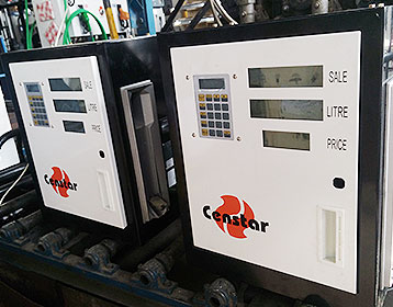
Automatic Tank Gauging; Electronic Line Leak Detection Censtar. Description. Solves your mechanical Leak testing Problems Intelligent electronic systems virtually eliminate "False Alarms" Self diagnostic system eliminates the required functional testing for mechanical leak detectors. No site shutdown to perform lph test
CN101287971A Tank gauging system Google Patents
A tank gauging system for sensing product parameters of a product contained in a tank is disclosed. The system comprises a microwave based level gauging unit and a temperature gauging unit.

SERVICE MANUAL Navistar
LoneStar® and ProStar® Chassis Built January, 2007 and After — ELECTRICAL CIRCUIT DIAGRAMS iii . REMOTE RADIO — N/AMP AND N/WIRED REMOTE AND N/DRIVER INTERFACE DISPLAY,
Franklin Fueling Systems Americas
Protect and extend the life of vital petroleum system electrical and data wiring with the Cable Tight™ wire management system. Get your entire company trained and certified on all courses in five days or get specialized training in one or two days with our live, Total System Solutions™ Training Workshops.
Well and Water System Diagram
Should be used on any system where the pump could develop pressure that exceeds the maximum system rating. (18) Pressure Gauge Measures water pressure in Pressure Tank. (19) Pressure Switch Signals the pump to start when the water system drops to a pre set low pressure, and to stop when the high pressure mark is reached. (20) Safety Switch

Radar Level Transmitters AutomationWiki
Radar level measurement technique offer extremely accurate and reliable detection of level in storage tanks and process vessels. The performance of radar level transmitters remains unaffected by heavy vapors and mostly all other physical properties of the fluid under level measurement (except dielectric constant of the liquid). Disadvantages
Fuel The Boeing 737 Technical Site
The fuel tank was instrumented with gas sample tubing and thermocouples to allow for a measurement of fuel tank inerting and heating during the testing. The FAA developed an in flight gas sampling system, integrated with eight oxygen analyzers, to continuously monitor the ullage oxygen concentration at eight different locations.
TANKERS & CHEMICAL
DRAFT GAUGING SYSTEM Schematic diagram Experience on board ships teaches how much problem give submersed electronic level sensor due to poor
Well head & pressure tank pictures / illustrations
Tank Tee Details. Notice the tank tee assembly is a quick and compact way to install the tank while incorporating a nipple & union, a recommended check valve, pressure switch, pressure gauge, pop off valve, and a faucet to get emergency water out ot the system even if the water is turned off to the house by the ball valve nearby. CLICK TO ENLARGE.
Diagnosing dual tank balance module The Truck Stop
For single fuel tank vehicles, the fuel gauge includes the following functions: The level sensor in the fuel gauge sender produces a resistance of about 40 ohms (Gas)/0 ohms (Diesel) empty and about 250 ohms (Gas)/90 ohms (Diesel) full. A short to ground in the sender or the wiring provides a fully empty indication.

Fuel System Diagrams Aeromotive, Inc
Fuel System Diagrams. Then return here for diagrams to complete your system. The following are the basic solutions to the most common systems. For more specific diagrams, or variables of the following, please call tech at 913 647 7300 Stealth 340 Diagrams Phantom 200 & 340, Stealth 340 Fuel Cells, Stealth 340 Performance Muscle Tanks.

Tank Gauging System ZYcj^hXdc9i^ EdgXYij
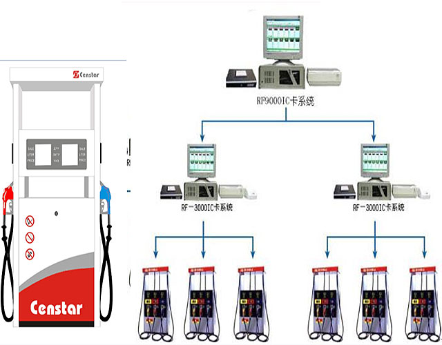
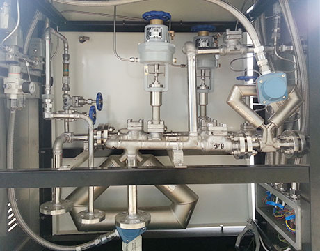
1. System Description The TankRadar Rex System is a monitoring and control system for tank level gauging. The system can interface various sensors, such as temperature and pressure sensors, for complete inventory control. There is a distributed intelligence in the various units of the system. The units continuously collect and process information.

circuit schematic Circuit Wiring Diagrams
The above schematic is just and illustration for the 1967 Ford F 100 and F 350 Wiring Diagram/Electrical System Schematic. This wiring diagrams applied for 1967 Ford Truck F 100 and F 350 series. Here you will find 13 diagrams depicting the 1967 Ford Truck F 100 wiring installation including truck auxiliary tank diagram, truck courtesy light wiring, exterior lights and turn signals, truck
Website
tank that is visible on the schematic image to view the details of the selected tank. The administrator can control the hotspots displayed on the schematic diagram by editing the file, located in the TMnData Language folders. This file contains the tank name and the co ordinates that are
Garnet Instruments Ltd. Liquid Level Measurement
Garnet is the source for leading edge solutions in liquid level measurement. Our patented SeeLeveL™ design for tank level gauging in transport tank truck applications not only provides accurate level information but is also the first totally automated spill prevention system for applications
Wiring diagram for 1998 chevrolet s10 2.2 fuel system Fixya
Haynes Manual 24071 includes wire diagrams for all components. On the injector you have a pink and dark blue wire both are hot and signal wires. The only ground in the system is on the fuel pump and sender unit. Diagram 12 26 in the haynes maual.
F2000EX EASY 02 28 00 ATA 28 FUEL SYSTEM CODDE 1
FUSELAGE TANK EMPTYING SEQUENCE The fuel gauging system and the fuel transfer sequence are monitored and controlled by the FQMC. The FQMC manages the fuel transfer sequences so that the fuel from the forward and rear tanks is used first. When these tanks are emplty, the FQMC uses fuel from LH and RH center and wings tanks.
Fuel Tank Schematic Wiring Diagram Database
Fuel system schematics and fuel gauge troubleshooting ford truck technical diagrams and schematics boat fuel tank wiring diagram magicalillusions help with dual tank selector valve wiring what is the wiring diagram for a chevrolet dual tank gas tank sending unit wiring diagram help page 1 iboats sst srs day tank manual simplex inc wiring